After you have succesfully installed the equipment to the car and configured the system, then it's time to validate logged data. Validating the data requires two steps
-
Log data in controlled manner
-
Analyse all logged channels and understand what you should get
This article targets to help you on both steps.
Log data in controlled manner
Purpose of this step is to have data available where you know what data to expect to see. For example with steering you can go from max left to max right. Then in data you should see steering values to from 100% to -100%. This is just done for all measured channels.
This step is easiest to do by keeping the car on a stand wheels up from ground/table, so you can test the throttle and speed signals. Alternatively you can create a small track on your drive way and generate the data with real driving but in a controlled situation.
So just turn on your car and radio. Check that your memory card is on place, USB cable is NOT connected and the unit logs data (solid blue and blinking white LED). After the checks are completed, you start following the procedure in chapter How to test channels and what result to expect? This procedure is just a suggestion, so feel free to use your own procedure if you know what you want to test.
After you completed the procedure, then turn off the equipment and transfer data to Connector in normal way.
When generating the run, we recommend to select "Use data file info" for session and create just a local file.
Validate the logged data
Now we assume you have been able to transfer the data file from Collector with help of Connector and data file is generated. If you need on this part, please read Connector Get Started page. If you need support how use/navigate in Analyzer, please read the Navigation and shortcuts page.
After you have the data file open in Analyzer, we recommend to use the Channel check tab to see all relevant data in one view.
Recommendation is to follow the Result column from How to test channels and what to except? to check the results.
If everything goes well, you can see the expected results in the data. If you don't see the expected result in the data, then it's good to really understand what the numbers are showing. For example is the data shape correct but values are wrong, then you can assume it's a calibration issue. If data has too much noise in it or data is just flat line, then you can suspect that you have connection issue or sensor installation is not correct. Of course it can be a hardware failure as well.
How to test channels and what result to expect?
|
Channel |
Action |
Result |
Data screenhot |
|---|---|---|---|
|
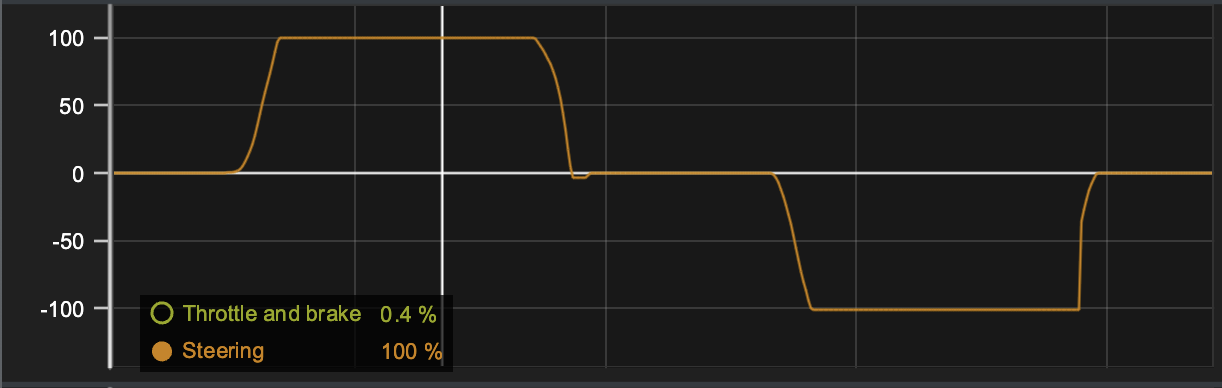
Steering |
Move steering from max left and keep it there for a second, then release steering back to 0. Do the same thing for max right. |
You should see steering channel values to from 0 to 100% when reaching max left, then steering value should go back to 0. When turning steering to right, steering channel value should go to -100%. |
|
|
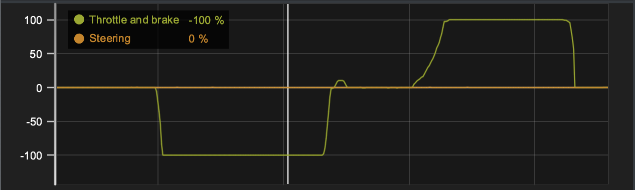
Throttle and brake |
Go from full throttle to max brake and then release the throttle back to neutral. |
Throttle & brake channel values should from -100% to +100% and then back to zero. In other words this indicates that from neutral to max brake then to full throttle. Brake values are always negative and throttle values positive. |
|
|
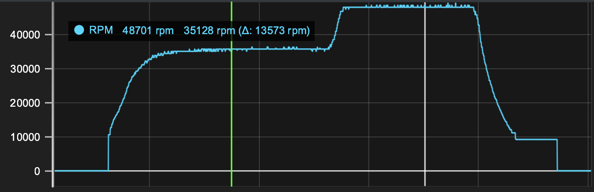
RPM |
Go from zero throttle to max throttle in two steps. From zero throttle first go around 50% throttle and keep it there for around 1 second. Then increase the throttle to 100% and keep it there for around 1 second. Finally release the throttle back to neutral. If you have wheel speed sensors, you can use same measurement to validate both all inputs at one go as the procedure is the same. |
RPM channel will give you two channels to the data which are RPM and Speed motor. First of all data shape must be following the same pattern on both channels. Speed value is just scaled value of the RPM. |
|
|
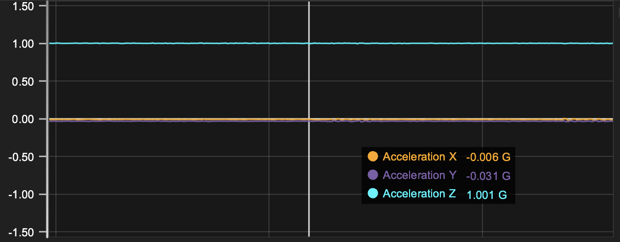
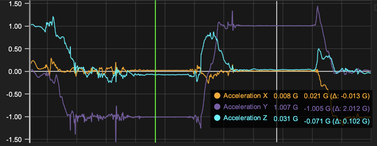
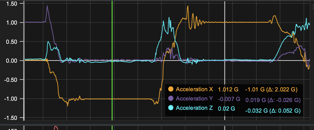
IMU accelerations |
Raise the car to air and turn it six different directions and keep the car in place for a second in each position. Positions as follows.
|
If you follow the actions, then you should see channel Acceleration X, Acceleration Y and Acceleration Z to change from -1 to +1 depending on chassis position.
When a car is in a static position, the only force acting on the IMU sensor is gravity, which is equivalent to 1G. However, the orientation of the car (sensor) relative to the direction of gravity will affect the values that the IMU records for each axis of acceleration. For example, if the sensor is mounted horizontally, then the X and Y axes will record values of 0G and the Z axis will record a value of 1G. |
|
|
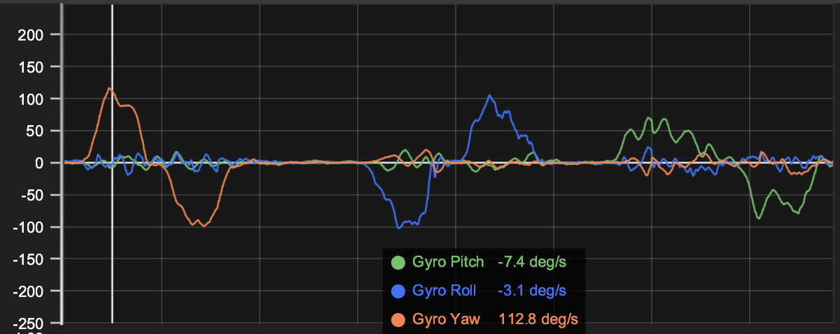
IMU gyro |
Raise the car to air and turn the car around the IMU in different directions. Try to do the movements with constant speed. Turn car as follows
|
IMU Gyro measures the angular velocity and not position. Gyro channels are name Gyro Yaw, Gyro Pitch and Gyro Roll. All channels will show 0 values when you keep the car in static position and as soon as you start to turn car around any of three axis, you will start to see values change. If you turn the car left 90 degrees, then you will see Yaw value to go positive as long the movement continues. After you stop, then value goes back to zero. When you start to turn the car back to original position, then values goes to negative. Value itself naturally depends on how quick you do the position change.
|
|
|
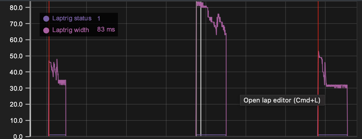
Lap and split |
Take the beacon and make sure it is turned off and lap mode is selected. Then place it close to Lap receiver and turn on for a second and then turn off. Wait e.g. 5 seconds and change mode to split and turn Beacon on and after one second turn it off. As a last step wait e.g. 5 seconds and change mode back to lap and turn Beacon on and after one second turn it off. |
Data should include one full lap and two sector times. In data you will see two lap markers and one split marker. The signal strength can be checked with channel Laptrig width. |
|
|
Analog input |
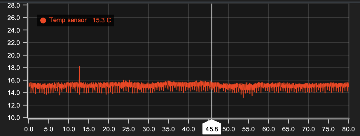
If you have temperature sensor connected to the analog port, then you can verify the measured data by measuring temperature from same surface with another temperature sensor like IR temp gun. If you know air temperature then alternatively you keep the temp sensor in the air and let it settle down to match air temperature. |
If you are using temp sensor to validate the data, you should be seeing temperature values in the data matching your expectations. Temperatures are always in Celcius degrees. |
|
|
Wheel speed |
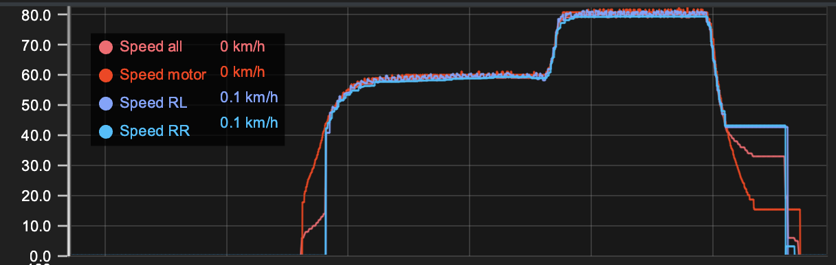
Go from zero throttle to max throttle in two steps. From zero throttle first go around 50% throttle and keep it there for around 1 second. Then increase the throttle to 100% and keep it there for around 1 second. Finally release the throttle back to neutral. If you have RPM sensor in the car, you can use same measurement to validate both all inputs at one go as the procedure is the same. |
With wheel speeds you need to be careful with the channels as it depends on what axle you have installed the sensors to. Let's assume you have installed your sensors to rear axle on both outdrives. In this case your speed channels are Speed RL and Speed RR. Recommendation is to put all speed channels into one line chart, so you can validate that all speed values are matching. Typically the speed values should be below 100 km/h even with full throttle. |
|
What if data is not correct or data channel is missing?
-
Recalibrate the input and check settings
-
Check wiring and sensors are connected to correct ports
-
Ask help in Discord or Facebook user group