TL0103002 - Motor sensor breakout
This sensor is only used with sensored electric motor. For nitro car, please check the TL0103004 - RPM sensor
Description
Sensor breakout is used for measuring RPM of an electric motor. It is also used as speed sensor by giving drive ratio values during configuration.
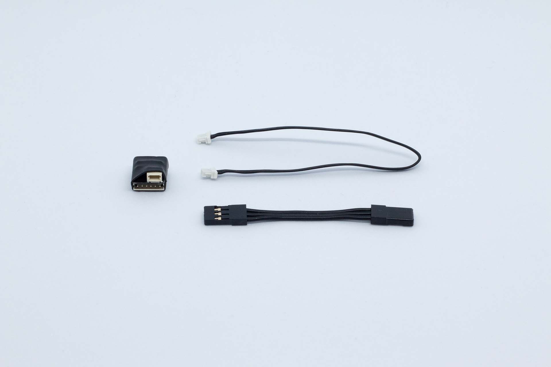
Package content
- 1 x Sensor breakout module
- 1 x 4cm motor sensor cable
- 1 x 15cm 3-pin cable
Installation
- Breakout board is installled between ESC and motor. Breakout module can be placed close to motor or close to ESC.
- Connect breakout module with 3-pin cable to RPM port in main unit.
Configuration
In normal situation Basic settings should be enough to configure the channel. Use Advanced parameters only if you know what you are doing.
Pinion and spur gear are important to set correctly as well if RPM/speed is measured from motor. These are set in General settings of the config. See Device configuration
Parameters for speed input RPM
| Parameter | Visibility | Type | Default value | Description |
|---|---|---|---|---|
| Enable | Basic | Boolean | yes | Parameter is used to enable the sensor for logging. Sensor is enabled if value is yes. |
| Radius | Basic | Decimal | 1 | Tire radius in meters. For example in 1/8th scale offroad good value is 0.052, so 5.2cm. Please notice! that this is radius and not diameter! |
| Internal ratio | Basic | Decimal | 1 | If speed is measured from the motor or from center differential, then typically this value needs to be set according to chassis specification. For example in AE RC8B3.2e the RPM can be measured from the motor. If the differential pinion is 13T and ring gear is 44T, then internal drive ratio and value for this parameter is 44/13 = 3.38 |
| Magnets | Basic | Integer | 1 | Here is defined how many magnets there is per rotation. Please notice! In electric motors motor divide the motor poles by two to get correct value. E.g. In 2-pole motor (1/10 scale motor) the value is 1 and with 4-pole motor (typically used in 1/8th scale) the value is 2. |
| Name | Advanced | String | Speed Motor | Channel name to be used in the exported data file. Data file will have own channel for all three dimensions and system will add the axis identifier after the channel name |
| Type | Advanced | Option | Motor RPM | Selection if this input is used for outdrive speed measurement or for RPM measurement. If Motor RPM is selected, then data file will have RPM and speed channel. If option General is used, then only speed channel will be visible. Please notice! Only one channel can have 'Motor RPM' option active. |
| Decimals | Advanced | Integer | 3 | Number of decimals in the logged data |
| Sampling time | Advanced | Option | 10ms | Sampling time for the channel |
| Filter | Advanced | Integer | 1 | Gives the possibility to filter accelerometer values. 1 = no filter, 9 = max filter |
| Unit | Advanced | Option | G Force (G) | Select the unit for exported data file. No effect on the calculation. |
| Size in bytes | Advanced | Option | 16bit | Defines data sample size in raw data. Options are 16bit value and 32bit value |
Example configuration
Here is an example how to set the RPM measurement channel for 2WD buggy (AE RC10B6.3) and same principles work for all electric cars. Below are some assumptions for the configuration.
- Pinion gear: 22T
- Spur gear: 78T
- Tire diameter: 8cm
- Internal driver ratio: Based on manual, it is 2.60:1
- Motor: normal 8.5T 540 size sensored brushless motor
To configure the input in Connector, please follow the steps below
- Open TestLogger Connector and either modify existing config or create new
- Do all changes in Basic mode
- Set pinion gear and spur gear on general tab
- Change to Speed configuration and modify input 1
- Set radius to 0.04. This the radius in meters which comes from the diameter (8cm / (2 * 100)) = 0.04m
- Set internal ratio to 2.6 based on manufacturer information or calculate it yourself from the gears
- Set magnets to 1 because the motor is two-pole motor, so the rotor has only one magnetic south pole.
- Save config to device
- Activate calibration mode and do a test run on bench to check if values are ok.