Hardware installation
The system is designed to be modular, so it is as easy as possible to install it in different car models, from 1/12th scale to 1/8th scale. To install the system, it is recommended to follow the steps below.
Input port types
Collector has multiple different port types and even the port physically looks the same, the purpose might be different.
- There is two ports for each channel, so it works as pass-through port.
- Connect, for example, the steering servo to one of the receiver ports and then connect an extra cable from the parallel receiver port to the receiver. Do the same thing for the ESC/throttle servo.
- The receiver port can be identified from 0.1" header connectors, which are typically used in receivers.
Collector system is powered via these receiver ports and any port can be used for powering the device. You can use both 6V and 7.4V BEC to power the device
- In analog port it's possible to use pretty much any analog sensor as long as maximum output level is +3.3V. The MCU can't measure higher voltage than 3.3V and input will break if input is higher than 5V
- Analog ports vary from 3-pin to 4-pin versions depending on Main unit specification. 3-pin version ports have one input channel and 4-pin port have two inputs in one port.
- IR receiver has own dedicated port in each main unit.
- This port cannot be used for any other purposes due to the special use case of measuring lap and split times.
- This port is always 3-pin port.
- Bus connector is used to connect special sensors like IMU and in the future many other sensors.
- It's possible connect multiple sensors to one port but splitter module is required for that use case.
- Bus connector is always 4-pin connector.
- Bus is based on I2C bus, but only supported sensors can be used
Do not add same type of sensor twice on the bus. E.g. Not possible to add two identical IMUs to bus. Two different type of IMUs must be used two measure two IMU values.
This is due to the reason that addresses on sensors are fixed and system doesn't work if there are multiple sensors with same address.
- Speed is used to measure wheel speeds and speed ports goes always in pairs so it's possible to measure speed from both outdrives on one axle.
- Speed ports are always 4-pin connectors
- Port is compatible only with Collector wheel speed sensors
- RPM port is special speed channel, so it can be used a single wheel sensor as well.
- Port can be used either with electric motor sensor breakout module or with separate RPM sensor.
- RPM port is always 3-pin connector
Installation Process
1. Find best location for the main unit (do not attach to chassis yet)
- As the receiver signals are routed via Collector, it is most convient to install the main unit close to receiver
- Remember to keep access to USB port or to the SD card slot. Otherwise the data download and configuration gets tricky.
- Collector can be installed horizontally or vertically.
- Finding the best place takes time and probably couple of tries before finding the best spot
- Please take a look for main unit specific instructions from unit page
2. Find locations for sensors
- Please take a look on the sensor specific instructions to correct installation
3. Route wires
- Cables are with 5cm increments to find optimal length cable for each sensor
- To make nice looking wiring, try to bundle or route the cables together
4. Attach components to chassis
- Use double sided tape
- Alternatively install sensors with brackets. Especially wheel speed sensors needs to be fixed with brackets.
5. Connect wires
- Remember to use cable ties to fix the wires
- Double check that cables are not going to touch any drivetrain parts
Sensor port pins are very thin and small, so pay attention that you don't use too much force installing the cables to main unit and sensors.
Example installation
Here is one sample installation for the equipment as inspiration
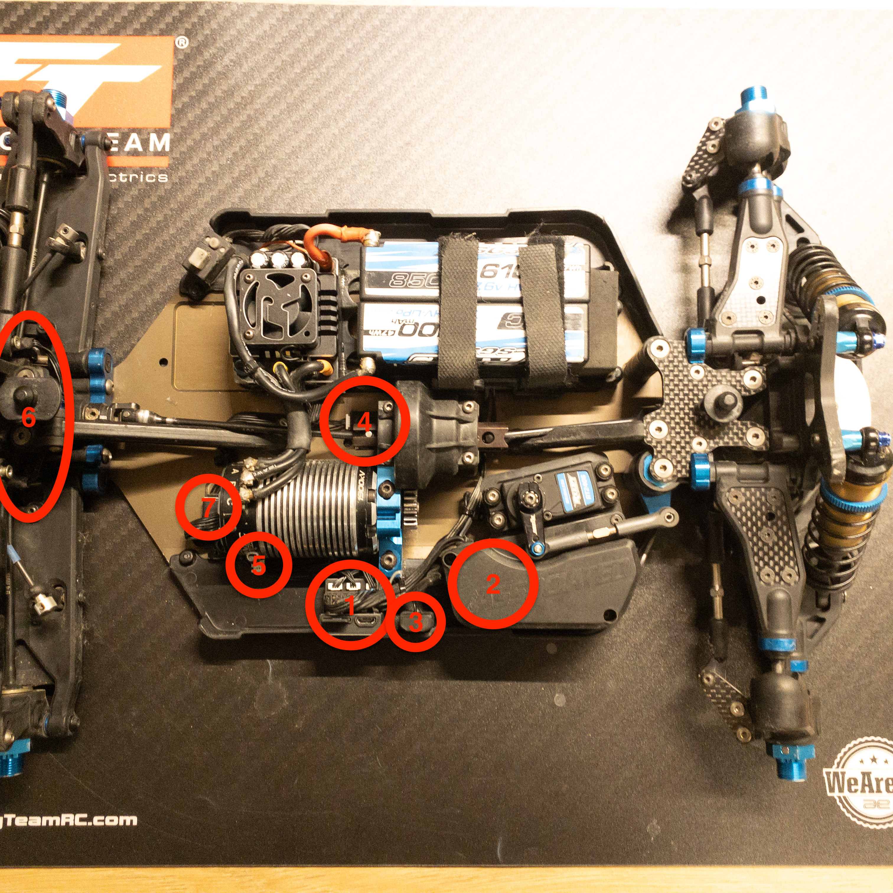
- Main unit
- Receiver location
- Lap receiver
- Inertial measurement unit (IMU)
- Temperature sensor
- Wheel speed sensors
- Electric motor sensor breakout