The system is designed to be modular, so it is as easy as possible to install it in different car models, from 1/12th scale to 1/8th scale. To install the system, it is recommended to follow the steps below.
Input port types
Collector has multiple different port types and even the port physically looks the same, the purpose might be different.
Installation Process
1. Find best location for the main unit (do not attach to chassis yet)
-
As the receiver signals are routed via Collector, it is most convient to install the main unit close to receiver
-
Remember to keep access to USB port or to the SD card slot. Otherwise the data download and configuration gets tricky.
-
Collector can be installed horizontally or vertically.
-
Finding the best place takes time and probably couple of tries before finding the best spot
-
Please take a look for main unit specific instructions from unit page
2. Find locations for sensors
-
Please take a look on the sensor specific instructions to correct installation
3. Route wires
-
Cables are with 5cm increments to find optimal length cable for each sensor
-
To make nice looking wiring, try to bundle or route the cables together
4. Attach components to chassis
-
Use double sided tape
-
Alternatively install sensors with brackets. Especially wheel speed sensors needs to be fixed with brackets.
5. Connect wires
-
Remember to use cable ties to fix the wires
-
Double check that cables are not going to touch any drivetrain parts
Sensor port pins are very thin and small, so pay attention that you don't use too much force installing the cables to main unit and sensors.
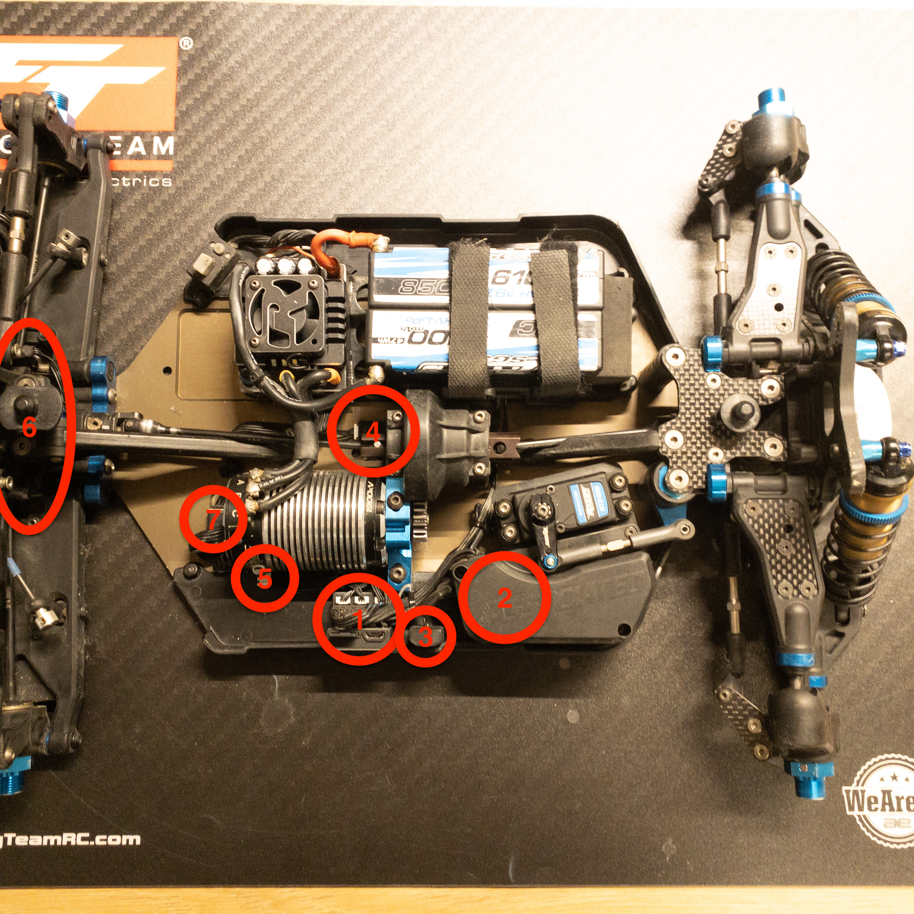
Example installation
Here is one sample installation for the equipment as inspiration
-
Main unit
-
Receiver location
-
Lap receiver
-
Inertial measurement unit (IMU)
-
Temperature sensor
-
Wheel speed sensors
-
Electric motor sensor breakout